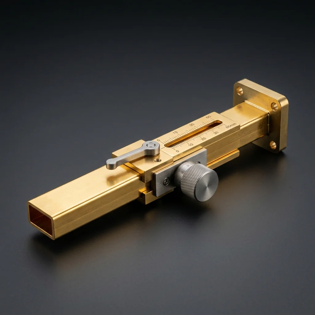
WR-28 Sliding Matched Termination
The WR-28 Sliding Matched Termination is a precision-engineered waveguide component that features an adjustable absorbing element for isolating and measuring residual reflections in test setups. It is specifically designed for the 26.5 - 40 GHz frequency range, serving as a critical building block in Ka-Band infrastructure.
The absorbing wedge is attached to a micrometer. By physically sliding the wedge back and forth, the phase of the termination reflection changes, allowing engineers to mathematically cancel out system errors. At Ka-Band frequencies (26.5-40 GHz), WR-28 components must balance high power handling with the onset of millimeter-wave skin depth challenges. The 0.280" x 0.140" aperture is the workhorse for modern 5G networks and LEO satellite constellations.
Key Features
Adjustable Match
Sliding mechanism allows precise positioning of the absorptive element for optimized impedance matching at the target frequency.
Calibration Grade
Designed to calibration kit standards for use as a matched load reference in TRL and other calibration procedures.
Low Residual VSWR
When properly adjusted, achieves very low return loss for accurate reference plane establishment and measurement confidence.
Precision Mechanism
Smooth, low-friction sliding action with precision-machined internal bore for repeatable, accurate adjustments.
Ka-Band Use Cases
5G NR Infrastructure
mmWave small cell routing
Satcom Terminals
Ka-band uplink/downlink
Airborne Radar
High-res targeting systems
Defense Comms
Secure point-to-point links
More Sliding Matched Terminations
Frequently Asked Questions
Why does the termination need to slide?+
No termination is perfect. By sliding the load over at least one-half wavelength, you can observe the phase ripple of the imperfection on a VNA. You can then mathematically separate the reflection of the load from the reflection of the actual device under test.
Why is WR-28 the standard for early mmWave 5G?+
WR-28 covers the critical 28 GHz and 39 GHz 5G NR frequency bands (n257, n258, n260, n261). Its physical size allows for high power handling at base stations while maintaining low insertion loss before the signal is distributed to the phased array antenna elements.
What is the theoretical cut-off frequency for WR-28?+
The dominant TE10 mode cut-off frequency for a standard WR-28 waveguide is approximately 21.08 GHz. This guarantees single-mode propagation throughout the entire Ka-Band.