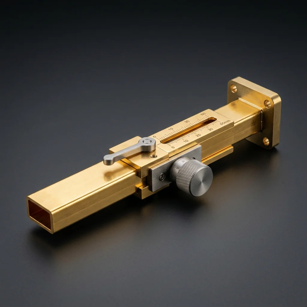
WR-12 Sliding Matched Termination
The WR-12 Sliding Matched Termination is a precision-engineered waveguide component that features an adjustable absorbing element for isolating and measuring residual reflections in test setups. It is specifically designed for the 60 - 90 GHz frequency range, serving as a critical building block in E-Band infrastructure.
The absorbing wedge is attached to a micrometer. By physically sliding the wedge back and forth, the phase of the termination reflection changes, allowing engineers to mathematically cancel out system errors. Operating in the 60-90 GHz E-Band, WR-12 is the backbone of modern 71-86 GHz high-capacity telecom links. The tiny 0.122" x 0.061" aperture requires anti-cocking flanges to prevent catastrophic misalignment.
Key Features
Adjustable Match
Sliding mechanism allows precise positioning of the absorptive element for optimized impedance matching at the target frequency.
Calibration Grade
Designed to calibration kit standards for use as a matched load reference in TRL and other calibration procedures.
Low Residual VSWR
When properly adjusted, achieves very low return loss for accurate reference plane establishment and measurement confidence.
Precision Mechanism
Smooth, low-friction sliding action with precision-machined internal bore for repeatable, accurate adjustments.
E-Band Use Cases
E-Band Backhaul
71-86 GHz point-to-point
Telecom Backbone
Fiber-optic extension
Collision Avoidance
Advanced vehicular radar
High-Res Imaging
Security scanning systems
More Sliding Matched Terminations
Frequently Asked Questions
Why does the termination need to slide?+
No termination is perfect. By sliding the load over at least one-half wavelength, you can observe the phase ripple of the imperfection on a VNA. You can then mathematically separate the reflection of the load from the reflection of the actual device under test.
Why is WR-12 critical for telecom backhaul?+
The FCC opened the 71-76 GHz and 81-86 GHz bands for ultra-high-capacity point-to-point microwave links. WR-12 components are the physical standard for routing these E-Band signals from the transceiver to the parabolic dish, enabling 10+ Gbps data rates where fiber is too expensive to lay.
What is an anti-cocking flange on WR-12?+
At E-Band frequencies, if a flange is bolted together unevenly (cocked), the microscopic gap will leak massive amounts of RF energy and ruin the VSWR. Anti-cocking flanges have an outer rim that guarantees the mating surfaces remain perfectly parallel during tightening.