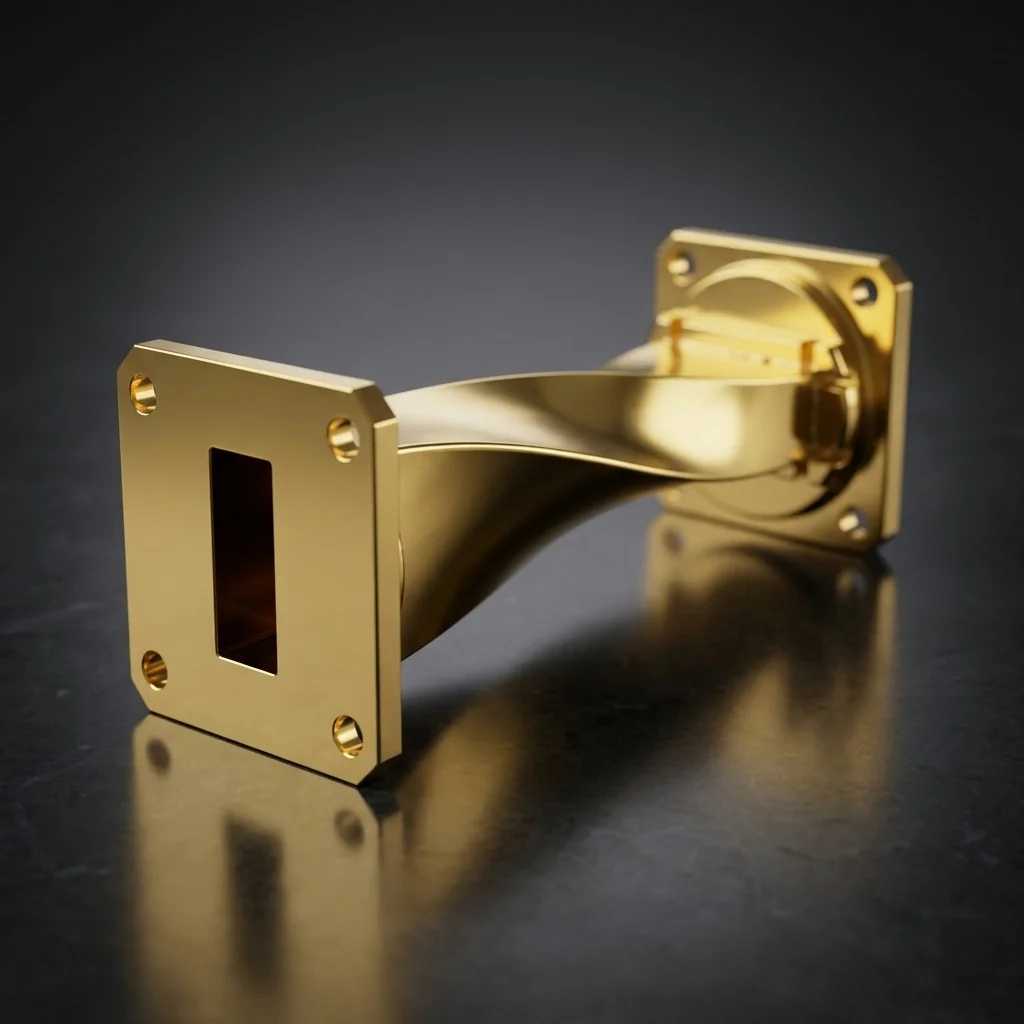
WR-12 Waveguide Twist
The WR-12 Waveguide Twist is a precision-engineered waveguide component that rotates the polarization of the electromagnetic wave by 90 degrees. It is specifically designed for the 60 - 90 GHz frequency range, serving as a critical building block in E-Band infrastructure.
The physical waveguide tube is gradually twisted along its longitudinal axis over a distance of at least two wavelengths, smoothly rotating the E-field and H-field without causing reflection. Operating in the 60-90 GHz E-Band, WR-12 is the backbone of modern 71-86 GHz high-capacity telecom links. The tiny 0.122" x 0.061" aperture requires anti-cocking flanges to prevent catastrophic misalignment.
Key Features
Gradual Twist Profile
Progressive twist geometry minimizes signal reflections and maintains TE10 mode integrity through the full 90-degree rotation.
Low Insertion Loss
Precision-machined interior walls ensure consistent waveguide dimensions throughout the twist length for minimal signal degradation.
Compact Design
Optimized twist length balances compact form factor with RF performance, fitting into tight waveguide assemblies without compromising signal quality.
Gold-Plated Construction
OFHC copper body with gold plating provides excellent conductivity, corrosion resistance, and consistent long-term electrical performance.
E-Band Use Cases
E-Band Backhaul
71-86 GHz point-to-point
Telecom Backbone
Fiber-optic extension
Collision Avoidance
Advanced vehicular radar
High-Res Imaging
Security scanning systems
More Waveguide Twists
Frequently Asked Questions
Why twist the waveguide instead of just rotating the flange?+
Many complex systems (like satellite feed horns or radar gimbals) require the signal to exit at a 90-degree angle to the transmitter. Since you cannot simply bolt two rectangular flanges together at 90 degrees without completely blocking the wave, a dedicated twist component must be used.
Why is WR-12 critical for telecom backhaul?+
The FCC opened the 71-76 GHz and 81-86 GHz bands for ultra-high-capacity point-to-point microwave links. WR-12 components are the physical standard for routing these E-Band signals from the transceiver to the parabolic dish, enabling 10+ Gbps data rates where fiber is too expensive to lay.
What is an anti-cocking flange on WR-12?+
At E-Band frequencies, if a flange is bolted together unevenly (cocked), the microscopic gap will leak massive amounts of RF energy and ruin the VSWR. Anti-cocking flanges have an outer rim that guarantees the mating surfaces remain perfectly parallel during tightening.