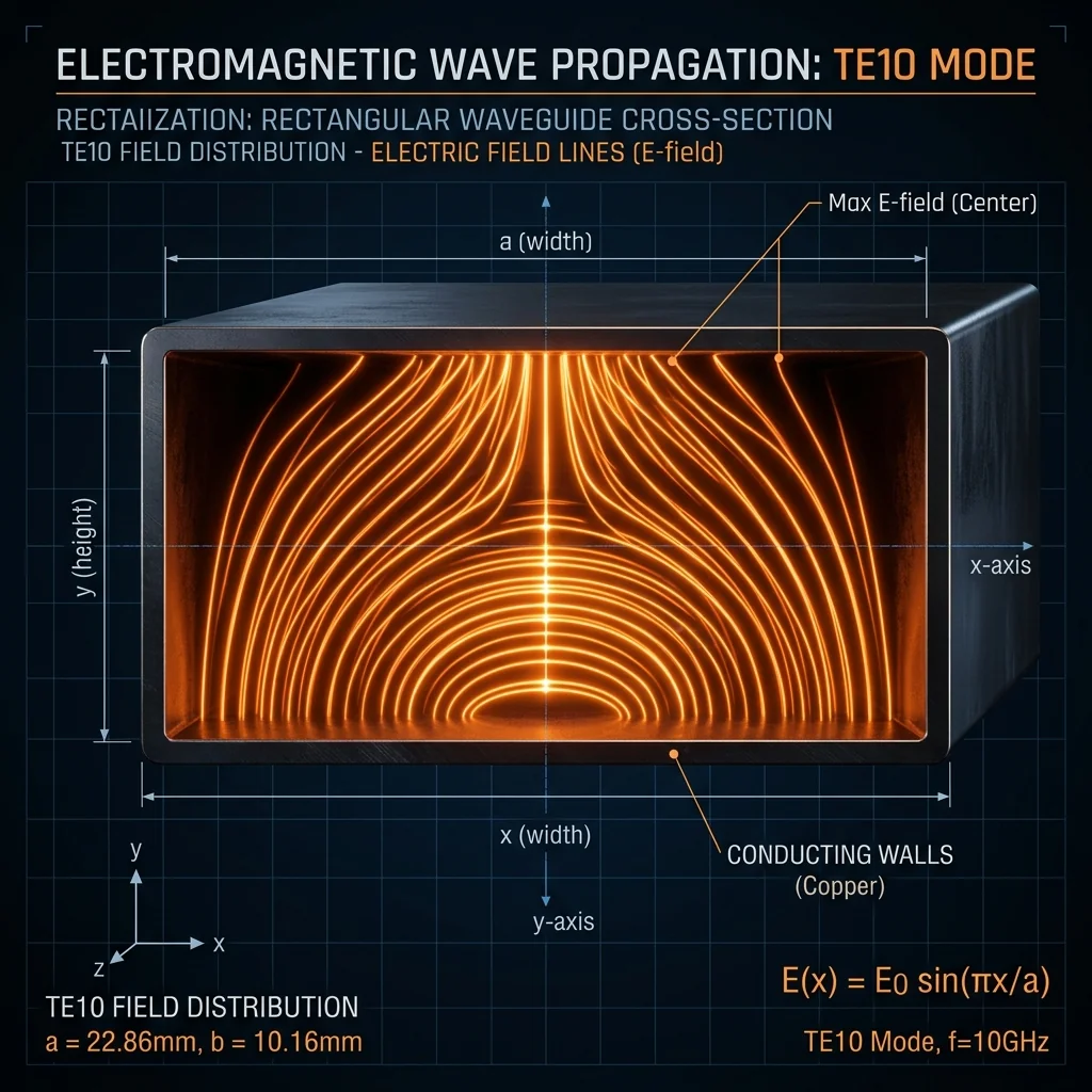
The Single-Mode Operating Principle
A rectangular waveguide is not just a hollow metal pipe. It is a resonant structure that supports specific electromagnetic field patterns, called modes, determined entirely by its internal dimensions and the frequency of the signal. Understanding which modes propagate and which do not is the foundation of all waveguide system design.
Every waveguide component that RF Essentials manufactures, from straight sections to E-plane bends to terminations, is designed to operate in the dominant TE10 mode. This is not arbitrary. The entire waveguide industry is built around the principle that only one mode should propagate at the operating frequency. When additional modes appear, they carry energy away from the intended signal path, create interference patterns, and corrupt measurements. Higher-order mode excitation is the most common cause of unexplained performance anomalies in millimeter wave systems.
Cutoff Frequency and the TE10 Mode
Each mode in a rectangular waveguide has a cutoff frequency below which it cannot propagate. The cutoff frequency is determined by the waveguide's internal dimensions (width "a" and height "b", where a > b).
fc(mn) = (c / 2) · √[(m/a)² + (n/b)²]
Where c = speed of light, m and n = mode indices, a = waveguide width, b = waveguide height
For the TE10 mode (m=1, n=0): fc = c / 2a. This is the lowest possible cutoff frequency and is why TE10 is called the "dominant" mode.
The WR designation system is built directly on this physics. WR-28 has an internal width of 7.112 mm (0.280 inches). The TE10 cutoff frequency is c / (2 × 7.112 mm) = 21.08 GHz. The specified operating range of WR-28 is 26.5 to 40 GHz. The lower limit (26.5 GHz) is set well above the TE10 cutoff to ensure the mode propagates efficiently. The upper limit (40 GHz) is set below the cutoff of the next higher-order mode to ensure that only TE10 propagates.
Higher-Order Mode Cutoffs
The next mode above TE10 in a standard rectangular waveguide (where a = 2b) is TE20, with a cutoff frequency of exactly twice the TE10 cutoff. This is why standard waveguide designations have an operating bandwidth ratio of approximately 1.5:1 (for example, WR-28: 26.5 to 40 GHz, a ratio of 1.51:1). The operating range sits entirely between the TE10 and TE20 cutoffs.
| WR Size | Internal Width (a) | TE10 Cutoff | TE20 Cutoff | Operating Range |
|---|---|---|---|---|
| WR-28 | 7.112 mm | 21.08 GHz | 42.15 GHz | 26.5 - 40.0 GHz |
| WR-15 | 3.759 mm | 39.88 GHz | 79.75 GHz | 50.0 - 75.0 GHz |
| WR-10 | 2.540 mm | 59.01 GHz | 118.03 GHz | 75.0 - 110.0 GHz |
| WR-06 | 1.651 mm | 90.79 GHz | 181.58 GHz | 110.0 - 170.0 GHz |
| WR-03 | 0.864 mm | 173.57 GHz | 347.14 GHz | 220.0 - 330.0 GHz |
What Excites Higher-Order Modes
In a perfectly straight, perfectly machined waveguide section, only the TE10 mode will propagate (assuming the signal frequency is within the single-mode band). Higher-order modes are excited by discontinuities: any abrupt change in the waveguide cross-section, direction, or symmetry.
Flange Misalignment
When two waveguide flanges are mated with a lateral offset, the step discontinuity at the junction acts as a mode converter. Energy from the TE10 mode is scattered into TE20, TE01, and other modes. At Ka-band and above, even a 25 μm misalignment generates detectable higher-order mode content. This is exactly why precision CPR flanges with dowel-pin alignment were developed.
Bends and Twists
E-plane and H-plane bends are designed to maintain TE10 propagation through the curve. But if the bend radius is too tight, or if the bend contains machining irregularities on the inner or outer radius, the curvature can excite the TE20 or TE01 mode. At RF Essentials, we specify minimum bend radii for each WR size and verify mode purity on every bend we ship.
Waveguide-to-Coaxial Transitions
The transition from coaxial to waveguide (or vice versa) is one of the most common sources of higher-order mode excitation. The coaxial probe that couples energy into the waveguide must be positioned precisely at the center of the broad wall. If the probe is offset, tilted, or incorrectly sized, it will preferentially excite asymmetric modes that cannot easily be filtered out downstream.
Lab Diagnostic: If your VNA measurement shows periodic ripple in S21 (insertion loss) that varies with frequency, you likely have higher-order mode interference. The ripple period corresponds to the beat frequency between the TE10 and the parasitic mode. The amplitude of the ripple indicates how much energy is in the unwanted mode. Tightening your flange connections and verifying transition alignment are the first steps toward resolving it.
Evanescent Modes Near Cutoff
Below its cutoff frequency, a mode does not suddenly disappear. It becomes "evanescent," meaning it decays exponentially with distance rather than propagating. Evanescent modes are important at waveguide junctions and discontinuities because they store reactive energy that affects the local impedance. This is why S-parameter measurements near the lower edge of a waveguide's operating band often show slightly elevated return loss: the TE10 mode is approaching its cutoff, its group velocity is slowing down, and evanescent mode interactions at every junction become more significant.
This is also why we recommend avoiding operation within 5% of the TE10 cutoff frequency. In that region, the waveguide impedance becomes highly dispersive, calibration accuracy degrades, and evanescent mode coupling at flanges creates measurement artifacts that are difficult to distinguish from genuine device characteristics.
Conclusion
Waveguide mode management is not an academic exercise. It is the practical foundation of every millimeter wave system. Every component in the signal chain, from the transition to the bends to the termination, must be designed and manufactured to preserve TE10 mode purity. When higher-order modes appear, they carry energy away from the intended path, create interference ripple in your measurements, and can couple into adjacent channels in multi-port systems. At RF Essentials, mode purity is a manufacturing specification, not an assumption. We verify it on every component we build.
RF Essentials manufactures precision waveguide components verified for TE10 mode purity across all WR sizes from WR-28 through WR-03. All products are made in the USA.