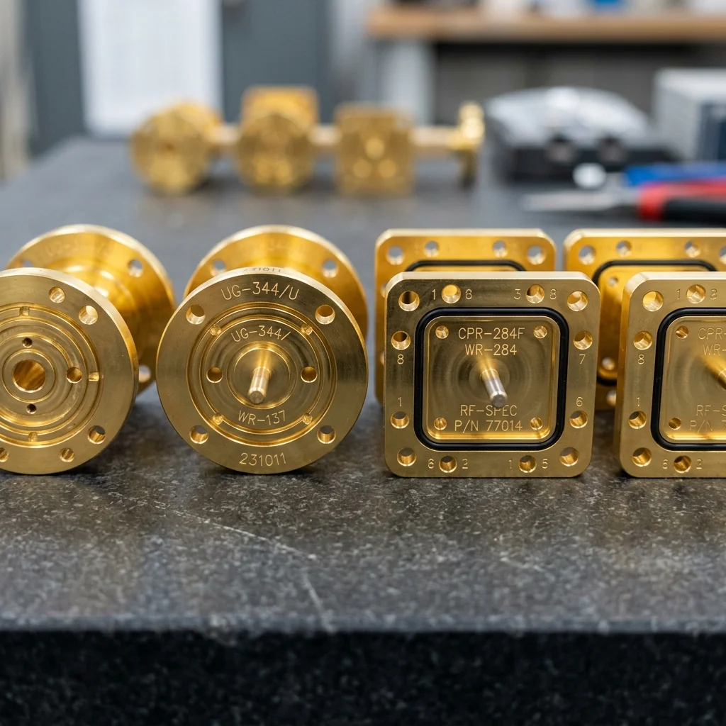
Why Flange Selection Matters More Than You Think
In over two decades of manufacturing waveguide components, I have seen more system failures caused by flange mismatches than by any other single mechanical issue. Engineers routinely spend weeks optimizing their waveguide taper designs, agonizing over insertion loss in their bends, and running finite element simulations on their transitions. Then they bolt everything together with mismatched flanges and wonder why their measured VSWR is 0.3 dB worse than the simulation predicted.
The waveguide flange is the mechanical interface where two waveguide sections meet. It seems simple: bolt two flat metal surfaces together with screws. But at millimeter wave frequencies, the tolerances required for a clean RF connection are measured in micrometers. A flange misalignment of just 25 micrometers at WR-10 (75 to 110 GHz) creates a step discontinuity in the waveguide aperture that generates a measurable reflection. Across a system with 20 flange connections, those reflections compound into significant performance degradation.
The Three Flange Families
The waveguide industry has converged on three primary flange standards, each with distinct alignment mechanisms and mechanical characteristics.
| Flange Type | Alignment Method | MIL-DTL-3922 Designation | Best For |
|---|---|---|---|
| UG (Cover / Choke) | Flat mating face, no precision alignment | UG-599, UG-383, etc. | General purpose, legacy systems, lower frequencies |
| CPR (Precision Dowel Pin) | Two precision dowel pins for repeatable alignment | CPR-137, CPR-112, etc. | High-frequency mmWave, precision measurement |
| CMR (Mini Precision) | Compact dowel pin pattern, smaller footprint | CMR-137, CMR-112, etc. | Space-constrained phased arrays, dense integration |
UG Flanges: The Legacy Standard
The UG flange family traces its lineage back to the earliest military microwave systems. The naming convention (UG-599, UG-383, UG-385, etc.) refers to specific MIL-DTL-3922 drawing numbers that define the bolt pattern, aperture dimensions, and mating face geometry for each WR size.
UG flanges use a cover-and-choke pairing system. The "cover" flange has a flat mating face surrounding the waveguide aperture. The "choke" flange has a circular groove machined into the mating face that creates a quarter-wave resonant trap, providing electrical continuity even if the two surfaces do not make perfect physical contact. This choke mechanism was a brilliant solution for the manufacturing tolerances of the 1950s and 1960s, when achieving a perfectly flat mating surface across the entire flange face was difficult.
The critical limitation of UG flanges is alignment. Standard UG flanges rely on the bolt holes for alignment, and bolt holes inherently have clearance. At frequencies below 18 GHz, this clearance is tolerable. At Ka-band and above, it is not. The waveguide aperture shrinks dramatically (WR-28 is only 7.112 mm wide), and any lateral shift between the two apertures creates a step that reflects energy.
CPR Flanges: The Precision Standard
The CPR (Connector, Precision, Rectangular) flange was developed specifically to solve the alignment problem at millimeter wave frequencies. Instead of relying on bolt holes for alignment, CPR flanges use two precision-ground dowel pins that press-fit into matching holes on the mating flange. These pins provide alignment accuracy on the order of 5 to 10 micrometers, far beyond what bolt-hole alignment can achieve.
At RF Essentials, all of our WR-28 through WR-03 products are available with CPR flanges as standard. When a customer orders a WR-10 straight waveguide section and a WR-10 E-plane bend, the CPR dowel pins guarantee that the apertures will align perfectly every time those two components are mated, regardless of which technician assembled the system.
Engineering Insight: CPR flanges are backward-compatible with UG flanges of the same WR size. The bolt pattern and aperture dimensions are identical. You can bolt a CPR flange to a UG flange; you simply will not benefit from the dowel pin alignment because the UG flange has no pin holes. This compatibility makes migration from UG to CPR a gradual process rather than a full system replacement.
CMR Flanges: The Compact Standard
As phased array systems and integrated RF assemblies have become denser, the physical footprint of the flange has become a constraint. CMR (Connector, Mini, Rectangular) flanges provide the same precision dowel-pin alignment as CPR flanges but in a significantly smaller bolt pattern. This allows tighter component spacing in multi-channel systems where dozens or hundreds of waveguide ports must fit within a limited panel area.
The trade-off is mechanical robustness. CMR flanges use smaller screws and thinner flange faces, making them less suitable for applications involving heavy vibration or high torque requirements. In a laboratory environment or an integrated electronic warfare pod, CMR flanges are excellent. For a field-deployed radar system subject to harsh environmental conditions, CPR or UG flanges remain the safer choice.
Cross-Compatibility Rules
The most common question I get from system engineers is: "Can I mate Vendor A's flange to Vendor B's component?" The answer depends entirely on whether both vendors are building to the same MIL-DTL-3922 drawing.
- UG to UG: Always compatible within the same WR size. The bolt pattern is standardized.
- CPR to CPR: Always compatible within the same WR size, provided the dowel pin diameter and spacing match the MIL drawing.
- CPR to UG: Mechanically compatible (same bolt pattern), but alignment is limited to bolt-hole accuracy. The dowel pins on the CPR flange will simply not engage.
- CMR to CMR: Compatible within the same WR size. Different bolt pattern from CPR/UG.
- CMR to CPR/UG: Not directly compatible. Different bolt patterns. Requires an adapter plate.
Flange Flatness and Surface Finish
Regardless of flange type, the mating face must be machined flat to within a few micrometers. At 110 GHz (WR-10), the free-space wavelength is 2.7 mm. A flange face that is bowed or warped by even 10 micrometers creates a gap between the two waveguide apertures. RF energy leaks into this gap, exciting parasitic modes and creating both radiation loss and inter-port coupling in multi-channel systems.
We machine all flange faces to a flatness specification of 5 micrometers or better and verify each unit with an optical flat before shipment. Gold plating on the mating face serves two purposes: it prevents oxide formation (which creates resistive contact points), and it provides a soft, conformal surface that fills microscopic voids when the flanges are torqued together.
Conclusion
The waveguide flange is the most mechanically simple component in the signal chain, and it is the one most likely to silently degrade your system performance. Choosing the correct flange standard, maintaining proper flatness tolerances, and understanding cross-compatibility rules are fundamental skills for any engineer building millimeter wave systems. At RF Essentials, we build every flange to MIL-DTL-3922 specifications because we know from experience that the flange interface is where sloppy manufacturing shows up first in the S-parameter data.
RF Essentials manufactures precision waveguide components with UG, CPR, and CMR flange options across all WR sizes. All products are made in the USA.