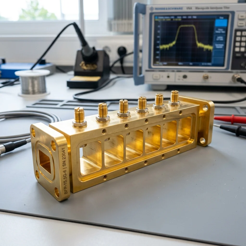
The Filter Problem at Millimeter Wave
Every RF system requires frequency selectivity. Whether you are building a radar receiver that must reject jamming signals, a satellite transponder that must separate uplink from downlink, or a 5G base station that must isolate adjacent frequency bands, the filter is the component that defines your spectral boundaries. At frequencies below 6 GHz, printed circuit board filters using microstrip or stripline technology provide adequate performance. But as we move into the millimeter wave bands, the losses in PCB substrates become prohibitive, and the only viable filter technology is the waveguide cavity filter.
At RF Essentials, we have built custom waveguide filters for clients in defense, satellite communications, and scientific instrumentation. The design process is fundamentally different from lumped-element or printed filter design because the resonant elements are three-dimensional electromagnetic cavities machined from solid metal. The performance ceiling is much higher, but so is the manufacturing complexity.
Cavity Resonator Fundamentals
A waveguide cavity resonator is a section of waveguide that is short-circuited at both ends. The electromagnetic energy bounces back and forth between the two shorting walls, creating a standing wave pattern. The cavity resonates at specific frequencies determined by its physical dimensions: length, width, and height.
fres = (c / 2) · √[(m/a)² + (n/b)² + (p/d)²]
Where a, b, d are the cavity dimensions and m, n, p are the mode indices. The resonant frequency is set by machining the cavity to precise dimensions.
The quality factor (Q) of a cavity resonator determines its frequency selectivity. Higher Q means a narrower bandwidth and sharper roll-off. Waveguide cavity Q factors at Ka-band typically range from 3,000 to 10,000, far exceeding what any printed circuit board resonator can achieve. This is because the energy storage mechanism is a three-dimensional standing wave in air, with losses occurring only in the thin skin depth layer on the cavity walls.
Filter Topologies Compared
| Topology | Coupling Mechanism | Typical Q | Best For | Manufacturing Complexity |
|---|---|---|---|---|
| Iris-Coupled Cavity | Thin metal walls with apertures (irises) | 5,000 - 10,000 | Narrowband waveguide BPF, satellite multiplexers | High (precision iris dimensions) |
| Post-Coupled Cavity | Metal posts between cavities | 3,000 - 7,000 | Moderate bandwidth, tunable filters | Medium (posts can be adjusted) |
| Interdigital | Parallel coupled resonator bars | 1,000 - 3,000 | Wideband, compact, sub-18 GHz | Low (simpler geometry) |
| Combline | Parallel shorted stubs with capacitive loading | 1,000 - 4,000 | Compact wideband, tunable with screws | Medium (tuning screw access) |
Iris-Coupled Waveguide Filters
The iris-coupled cavity filter is the gold standard for narrowband filtering at millimeter wave frequencies. Each resonant cavity is separated from its neighbors by a thin metal wall (the iris) containing a precisely dimensioned aperture. The size of the aperture controls the coupling coefficient between adjacent cavities, which in turn determines the filter bandwidth and passband shape.
The critical manufacturing challenge is the iris aperture dimension. At WR-28 (Ka-band), a 1% change in iris width shifts the coupling coefficient by approximately 3%, which can transform a 500 MHz bandwidth filter into a 515 MHz bandwidth filter with measurably degraded return loss. We machine iris plates using wire EDM (electrical discharge machining) to achieve aperture tolerances of 10 micrometers or better.
Interdigital and Combline Filters
Below 18 GHz, interdigital and combline filters provide a more compact alternative to waveguide cavities. These filters use arrays of parallel metal bars (resonators) housed inside a rectangular trough. The bars alternate in orientation (interdigital) or are all grounded at one end with capacitive tuning screws at the other (combline). These topologies sacrifice some Q factor compared to pure waveguide cavities, but their smaller size and easier tunability make them practical for many systems.
Tuning and Post-Manufacturing Adjustment
No matter how precise the CNC machining, a waveguide filter will always require some degree of tuning after assembly. Tuning screws that protrude into the resonant cavities allow fine adjustment of the resonant frequency and coupling. The tuning process is performed on a VNA, with the technician adjusting each screw while monitoring the S21 (transmission) and S11 (reflection) responses in real time.
At RF Essentials, we perform all filter tuning in-house and provide full S-parameter data with every shipment. The customer receives a filter that is verified to meet their specific passband, rejection, and return loss requirements across the full operating temperature range.
Conclusion
RF filter design at millimeter wave frequencies is a discipline where electromagnetic theory meets precision manufacturing. The cavity dimensions define the resonant frequency, the iris dimensions define the bandwidth, and the surface finish of the cavity walls defines the insertion loss. There are no shortcuts: a high-performance filter requires high-precision machining, careful material selection, and skilled tuning. At RF Essentials, we bring all three to every custom filter we build.
RF Essentials designs and manufactures custom waveguide filters for defense, satellite, and instrumentation applications. All products are made in the USA.