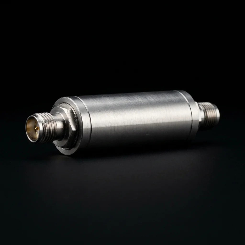
The Role of the Bandpass Filter in RF Systems
A bandpass filter passes signals within a defined frequency range and rejects everything outside it. In a radar receiver, the bandpass filter sits directly after the antenna and before the low-noise amplifier. It blocks out-of-band interference, image frequencies, and broadband noise that would otherwise desensitize the receiver. In a satellite transponder, bandpass filters define the individual channel allocations within the transponder's total bandwidth. The filter's selectivity, insertion loss, and power handling directly impact system performance.
At millimeter wave frequencies, waveguide cavity bandpass filters are the only practical solution when you need simultaneously high selectivity (narrow passband), low insertion loss, and high power handling. Printed circuit board filters cannot achieve the Q factors required for sharp roll-off, and their substrate losses are prohibitive above 30 GHz.
Iris-Coupled Filter Architecture
The most common waveguide bandpass filter topology is the iris-coupled cavity filter. It consists of a series of resonant cavities connected in cascade. Each cavity is a half-wavelength section of waveguide, and adjacent cavities are separated by thin metal walls containing precisely dimensioned rectangular apertures (irises).
Design Parameters: The filter's center frequency is set by the cavity length. The bandwidth is controlled by the iris aperture dimensions. The number of cavities determines the filter order, which sets the roll-off steepness (more cavities = sharper transition from passband to stopband). A 4-cavity filter typically provides 30 to 40 dB of rejection at twice the passband bandwidth from center.
Specification Parameters
| Parameter | Typical Range (Ka-band) | Design Impact |
|---|---|---|
| Center Frequency | 26.5 to 40.0 GHz | Set by cavity physical length |
| 3-dB Bandwidth | 100 MHz to 4 GHz | Controlled by iris coupling dimensions |
| Insertion Loss | 0.5 to 2.0 dB | Lower with higher Q (larger cavities, better surface finish) |
| Return Loss | > 15 dB across passband | Set by proper tuning of each cavity |
| Out-of-Band Rejection | 40 to 80 dB | Increases with filter order (number of cavities) |
| Power Handling | 10 W to 1,000+ W CW | Limited by voltage breakdown in narrow irises |
The Tuning Process
After CNC machining and assembly, every waveguide bandpass filter requires precision tuning. Each cavity has a tuning screw that protrudes through the broad wall of the waveguide into the resonant volume. Adjusting this screw changes the cavity's resonant frequency by perturbing the electromagnetic field distribution.
The tuning process is performed iteratively on a VNA. The technician connects the filter between the VNA's two ports and observes the S21 (transmission) and S11 (reflection) responses in real time. Starting from the input cavity and working toward the output, each cavity is tuned to its target resonant frequency. The inter-cavity coupling (determined by the fixed iris dimensions) establishes the overall passband shape. The tuning screws provide the fine frequency adjustment needed to center the passband and optimize the return loss ripple.
This process requires significant skill and experience. Over-tuning one cavity can shift the entire passband shape, requiring the technician to back-track and re-adjust multiple cavities. At RF Essentials, our tuning technicians have decades of combined experience and use automated VNA data capture to document every filter's final response.
Applications
Satellite Communications
In a communications satellite, the input multiplexer (IMUX) uses a bank of waveguide bandpass filters to separate the received uplink signal into individual transponder channels. Each filter must provide sufficient adjacent-channel rejection to prevent cross-talk, while maintaining low enough insertion loss to preserve the system's noise figure. These filters operate in the harsh thermal environment of space, and their center frequency must remain stable across a 200°C temperature range.
Electronic Warfare
EW receivers use tunable waveguide filters (with motorized tuning screws) to scan across the threat spectrum and isolate individual radar emissions for identification. The filter must tune rapidly across a wide frequency range while maintaining consistent passband shape and rejection at each frequency setting.
Conclusion
The waveguide bandpass filter is a precision component where electromagnetic design, manufacturing accuracy, and tuning skill converge. Its performance defines the spectral boundaries of every subsystem it serves. At RF Essentials, we manufacture custom waveguide filters to customer specifications, delivering fully tuned and verified assemblies with complete S-parameter documentation.
RF Essentials designs and manufactures custom waveguide bandpass filters for defense, satellite, and instrumentation applications. All filters are tuned and verified in-house.