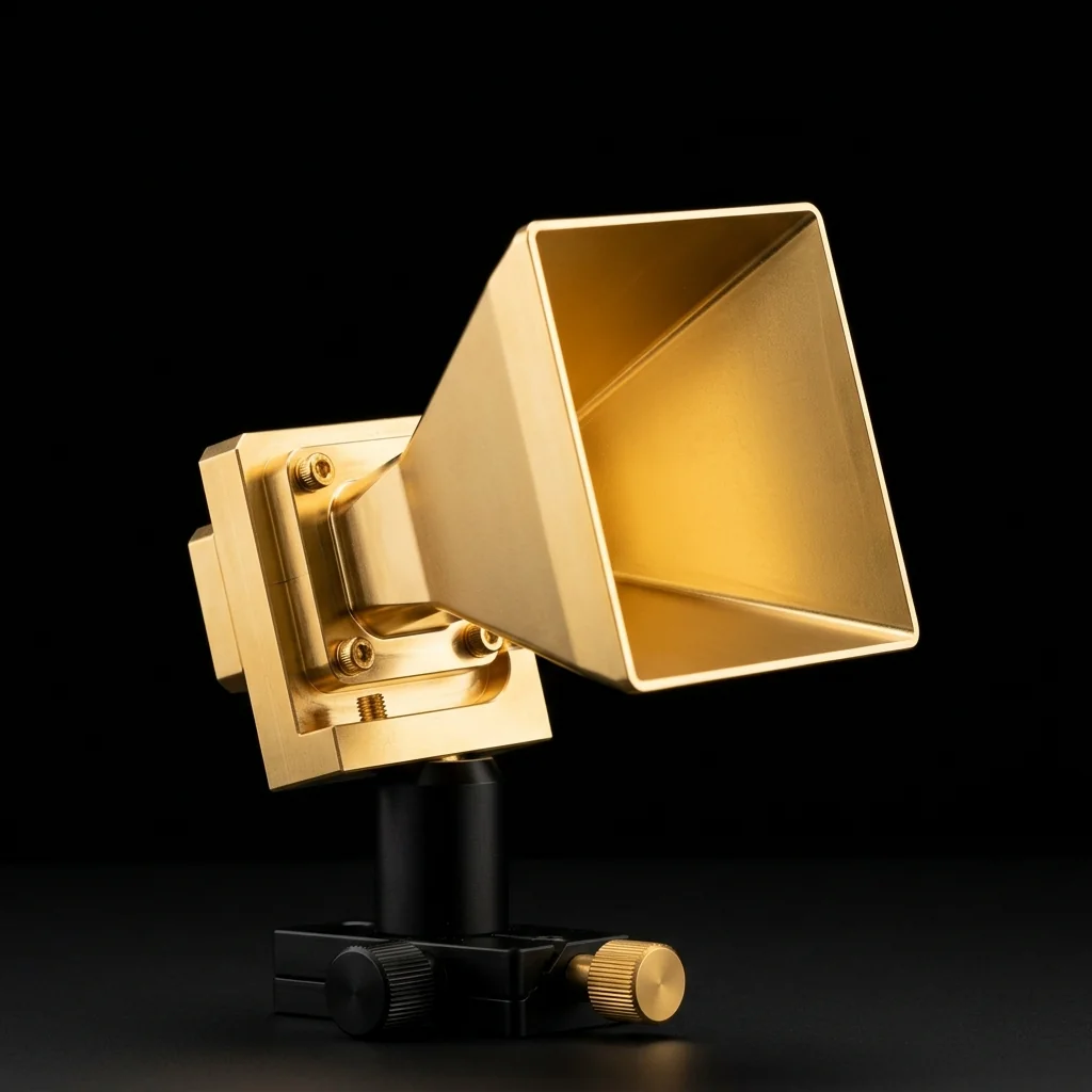
Standard Gain
Horn Antennas
Precision-machined pyramidal horn antennas with known, traceable gain values. The industry-standard reference antenna for calibration, measurement, and RF system verification from 8.2 GHz to 750 GHz.
The Calibration Reference Standard
RF Essentials standard gain horn antennas are precision-manufactured pyramidal horns with known, repeatable gain values. They serve as reference antennas in antenna measurement systems, calibration setups, and RF verification environments where traceable performance is mandatory.
Optimized horn geometry produces well-defined beam patterns, stable polarization characteristics, and low VSWR across the full operating band. Available in 10, 15, 20, and 25 dBi gain configurations across 17 waveguide bands spanning X-band through submillimeter frequencies. Each horn ships with measured gain data and a calibration certificate.
Standard Gain Horns by Waveguide Band
Each row represents a standard waveguide band. Multiple gain levels (10, 15, 20, 25 dBi) are available per band. All horns feature rectangular waveguide input with standard UG-series flanges. Custom gain values and waveguide interfaces available on request.
17 Waveguide Bands| WR Band | Waveguide Band | Frequency Range | Gain Options | Polarization | Flange |
|---|---|---|---|---|---|
| WR-90 | X-Band | 8.2 – 12.4 GHz | 15 dBi | Linear | UG-39/U |
| WR-75 | Xs-Band | 10.0 – 15.0 GHz | 25 dBi | Linear | UG-344/U |
| WR-62 | Ku-Band | 12.4 – 18.0 GHz | 20 dBi | Linear | UG-419/U |
| WR-42 | K-Band | 18.0 – 26.5 GHz | 10, 15, 20 dBi | Linear | UG-595/U |
| WR-28 | Ka-Band | 26.5 – 40.0 GHz | 10, 15, 20, 25 dBi | Linear | UG-599/U |
| WR-22 | Q-Band | 33.0 – 50.0 GHz | 15, 20, 25 dBi | Linear | UG-383/U |
| WR-19 | U-Band | 40.0 – 60.0 GHz | 10, 15, 20, 25 dBi | Linear | UG-383/U-M |
| WR-15 | V-Band | 50.0 – 75.0 GHz | 10, 15, 20, 25 dBi | Linear | UG-385/U |
| WR-12 | E-Band | 60.0 – 90.0 GHz | 10, 15, 20, 25 dBi | Linear | UG-387/U |
| WR-10 | W-Band | 75.0 – 110.0 GHz | 10, 15, 20, 25 dBi | Linear | UG-387/U |
| WR-8 | F-Band | 90.0 – 140.0 GHz | 10, 15, 20, 25 dBi | Linear | UG-387/U-M |
| WR-6 | D-Band | 110.0 – 170.0 GHz | 15, 20, 25 dBi | Linear | UG-387/U |
| WR-5 | G-Band | 140.0 – 220.0 GHz | 10, 15, 20, 25 dBi | Linear | UG-387/U-M |
| WR-4 | H-Band | 170.0 – 260.0 GHz | 25 dBi | Linear | UG-387/U-M |
| WR-3 | J-Band | 220.0 – 325.0 GHz | 15, 25 dBi | Linear | UG-387/U-M |
| WR-2.8 | Sub-mm | 260.0 – 400.0 GHz | 25 dBi | Linear | UG-387/U-M |
| WR-1.5 | Sub-mm | 500.0 – 750.0 GHz | 25 dBi | Linear | UG-387/U-M |
Gain values are nominal at mid-band. Each horn ships with measured gain data. Contact engineering for calibration certificates and custom configurations.
Need a specific band or gain configuration?
Our engineering team can provide pricing, datasheets, calibration data, and custom waveguide configurations for any standard gain horn in the catalog.
Design & Construction
Each horn provides a precisely characterized gain value traceable to measurement standards. This known reference is essential for substitution-method gain measurements and system calibration.
Optimized horn flare geometry and precision waveguide interfaces deliver low VSWR across the full operating band, minimizing reflections and ensuring accurate power transfer in measurement setups.
Controlled horn geometry produces stable, well-defined beam patterns with consistent sidelobe behavior. Repeatable from unit to unit for reliable measurement comparisons.
Maintains consistent linear polarization across the operating frequency band with low cross-polarization levels, supporting accurate polarization-sensitive measurements.
Horn bodies and waveguide sections are CNC-machined from solid aluminum with controlled surface finishes. Critical for maintaining dimensional tolerances at millimeter-wave and submillimeter frequencies.
All horns use standard UG-series rectangular waveguide flanges for direct integration with existing test equipment, VNAs, signal sources, and measurement receivers.
Where Our Standard Gain Horns Perform
Standard gain horn antennas are the foundational reference tool in antenna measurement and RF system verification. Their known gain values and predictable patterns make them indispensable wherever traceable measurements are required.
- Antenna Gain Calibration
- Near-Field & Far-Field Test Ranges
- RF System Characterization
- Radar Cross-Section (RCS) Testing
- EMC Pre-Compliance Testing
- 5G / 6G mmWave Research
- SATCOM Ground Station Verification
- Submillimeter-Wave Research

Other Antenna Categories
Horn Lens Antennas
Lens-corrected horns with dielectric lenses for enhanced directivity, lower sidelobes, and tighter beam patterns than standard horns.
View CategoryCassegrain Antennas
Dual-reflector systems with compact rear-mounted feed for higher aperture efficiency and reduced blockage.
View CategoryFrequently Asked Questions
A standard gain horn is a precision-manufactured pyramidal or conical horn antenna with a known, traceable gain value. Engineers use them as reference antennas for calibrating measurement systems, verifying antenna performance, and establishing traceable gain standards in RF test environments.
RF Essentials standard gain horns are available across 17 waveguide bands from WR-90 (8.2 GHz) through WR-1.5 (750 GHz). Coverage spans X-band through submillimeter frequencies. Multiple gain levels (10, 15, 20, 25 dBi) are available per band.
Standard gain horns are offered in 10, 15, 20, and 25 dBi nominal gain configurations per waveguide band. Higher gain models use larger apertures for narrower beamwidth. Lower gain models are more compact and suited for near-field probing or confined test setups.
The horn serves as a reference antenna with a known gain value. By comparing the measured signal through the device under test against the known reference, engineers can accurately determine unknown antenna gain, system losses, and path characteristics. This substitution method is the foundation of most antenna measurement protocols.