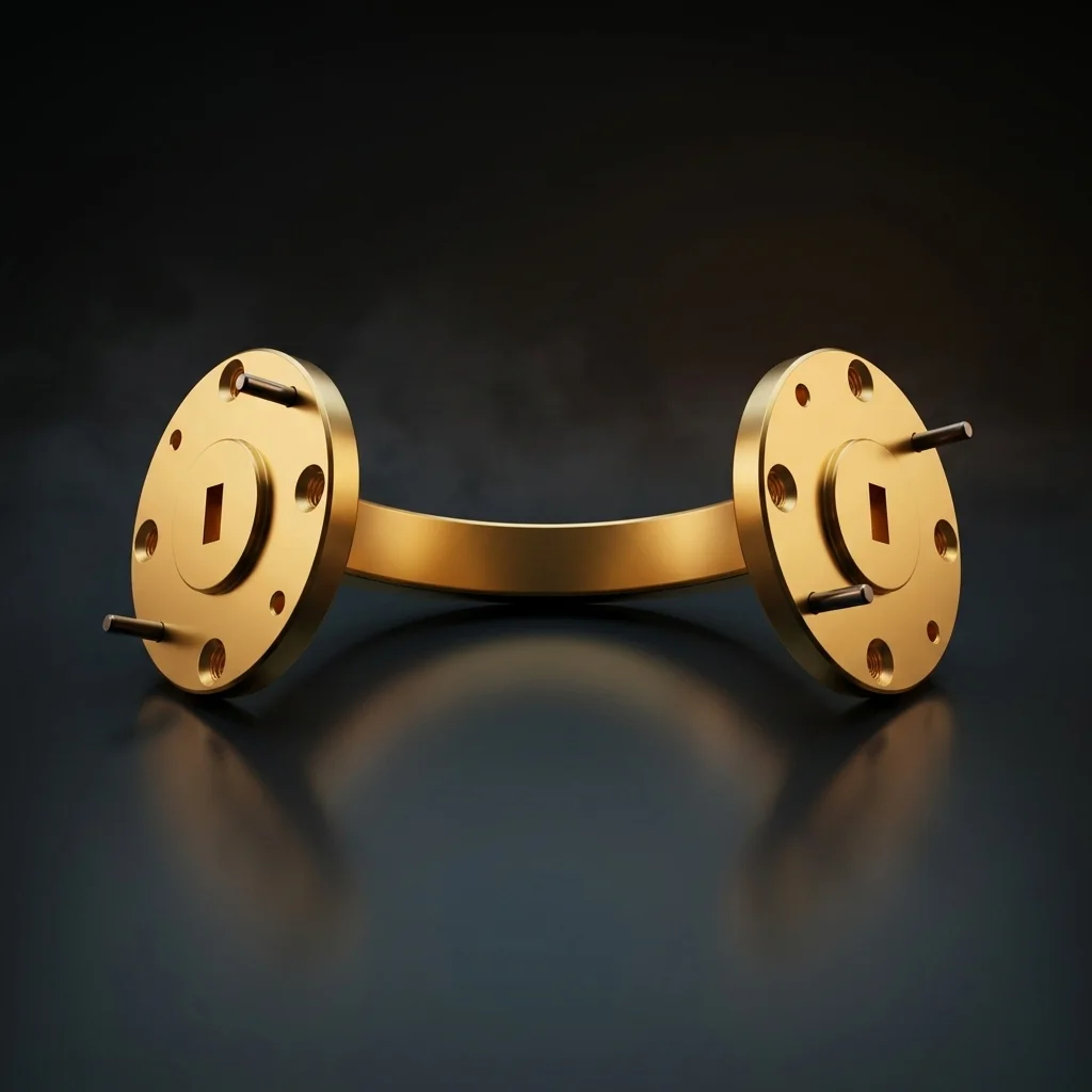
WR-12 E-Plane Bend
The WR-12 E-Plane Bend is a precision-engineered waveguide component that redirects millimeter-wave signals by 90 degrees in the narrow wall (E-field) plane. It is specifically designed for the 60 - 90 GHz frequency range, serving as a critical building block in E-Band infrastructure.
E-plane bends curve along the shorter dimension of the rectangular waveguide cross-section, providing vertical signal routing while maintaining phase integrity. Operating in the 60-90 GHz E-Band, WR-12 is the backbone of modern 71-86 GHz high-capacity telecom links. The tiny 0.122" x 0.061" aperture requires anti-cocking flanges to prevent catastrophic misalignment.
Key Features
E-Plane Geometry
Bend follows the narrow wall (shorter dimension) of the waveguide, routing signals vertically while maintaining the broad-wall dimension.
Low Insertion Loss
Optimized bend radius and CNC-machined interior walls ensure minimal signal degradation through the 90-degree turn.
Precision CNC Machined
Each bend is machined from a solid billet of OFHC copper, maintaining tight dimensional tolerances throughout the bend radius.
Gold-Plated Construction
Gold plating provides excellent conductivity, corrosion resistance, and consistent electrical performance over the component's service life.
E-Band Use Cases
E-Band Backhaul
71-86 GHz point-to-point
Telecom Backbone
Fiber-optic extension
Collision Avoidance
Advanced vehicular radar
High-Res Imaging
Security scanning systems
More E-Plane Bends
Frequently Asked Questions
What is the difference between an E-plane and H-plane bend?+
An E-plane bend curves the waveguide along its narrow wall (shorter dimension), shifting the electric field vertically. An H-plane bend curves along the broad wall (wider dimension), shifting the magnetic field horizontally.
Why is WR-12 critical for telecom backhaul?+
The FCC opened the 71-76 GHz and 81-86 GHz bands for ultra-high-capacity point-to-point microwave links. WR-12 components are the physical standard for routing these E-Band signals from the transceiver to the parabolic dish, enabling 10+ Gbps data rates where fiber is too expensive to lay.
What is an anti-cocking flange on WR-12?+
At E-Band frequencies, if a flange is bolted together unevenly (cocked), the microscopic gap will leak massive amounts of RF energy and ruin the VSWR. Anti-cocking flanges have an outer rim that guarantees the mating surfaces remain perfectly parallel during tightening.