Engineering
Resources
Free RF calculators, conversion tools, and learning resources for microwave and millimeter wave engineers. Built by engineers, for engineers.
RF Calculators
Interactive engineering calculators for common RF and millimeter wave design tasks. Bookmark these and keep them in your workflow.
Takes any one of these three values as input and instantly converts to the other two. These parameters all describe impedance matching quality but engineers encounter them in different specs and datasheets, so they are constantly needing to translate between them.
Open CalculatorCalculates the total system noise figure for a chain of RF components (LNAs, filters, mixers, cables) using the Friis noise equation. Input the gain and noise figure of each stage and get your overall system noise performance.
Open CalculatorConverts between milliwatts, watts, dBm, and dBW. Engineers live in logarithmic units and need to move between linear and log power constantly. Simple but used dozens of times a day.
Open CalculatorCalculates the physical trace width needed to achieve a target impedance (typically 50 ohms) on a PCB, given substrate thickness, dielectric constant, and frequency. Also computes effective dielectric constant and propagation delay.
Open CalculatorComputes signal attenuation over distance at a given frequency using the Friis transmission equation. Used for link budget planning, antenna selection, and system architecture.
Open CalculatorCalculates how deep current penetrates into a conductor at a given frequency for common materials like copper, aluminum, gold, and silver. Important for understanding conductor losses, plating thickness, and waveguide performance at mmWave frequencies.
Open CalculatorDetermines the cutoff frequency for standard rectangular and circular waveguide sizes across dominant and higher order modes. Use this when selecting waveguide components to ensure correct frequency range and mode operation.
Open CalculatorA multi-input tool that brings together transmit power, antenna gains, cable losses, free space path loss, and system noise figure to determine whether a communications link closes with adequate margin.
Open CalculatorSee exactly how much transmitted power is lost to impedance mismatch at any VSWR. Interactive calculator, visual chart, and complete reference table from 1.006:1 to 3.5:1 with return loss, mismatch loss, and reflection coefficient.
Open ReferenceHow much power can your coaxial connector handle? Interactive chart and selection tool showing average CW power ratings for 9 connector types (Type N, SMA, 2.92mm, 1.85mm, and more) from 1 GHz to 110 GHz.
Open ReferenceTE11 mode circular waveguide pipe sizes and flange dimensions for antenna feed applications. 35 standard sizes from Ku-band (12.4 GHz) through G-band (220 GHz) with UG flange designations and technical drawings.
Open ReferenceRF Glossary
A comprehensive reference of terms, acronyms, and definitions used across RF, microwave, and millimeter wave engineering. From antenna parameters to waveguide specifications, this glossary covers the vocabulary you encounter in datasheets, design reviews, and system specifications.
Whether you're a seasoned RF engineer or new to the field, use this as a quick reference for technical terminology and standard definitions.
Waveguide Flanges
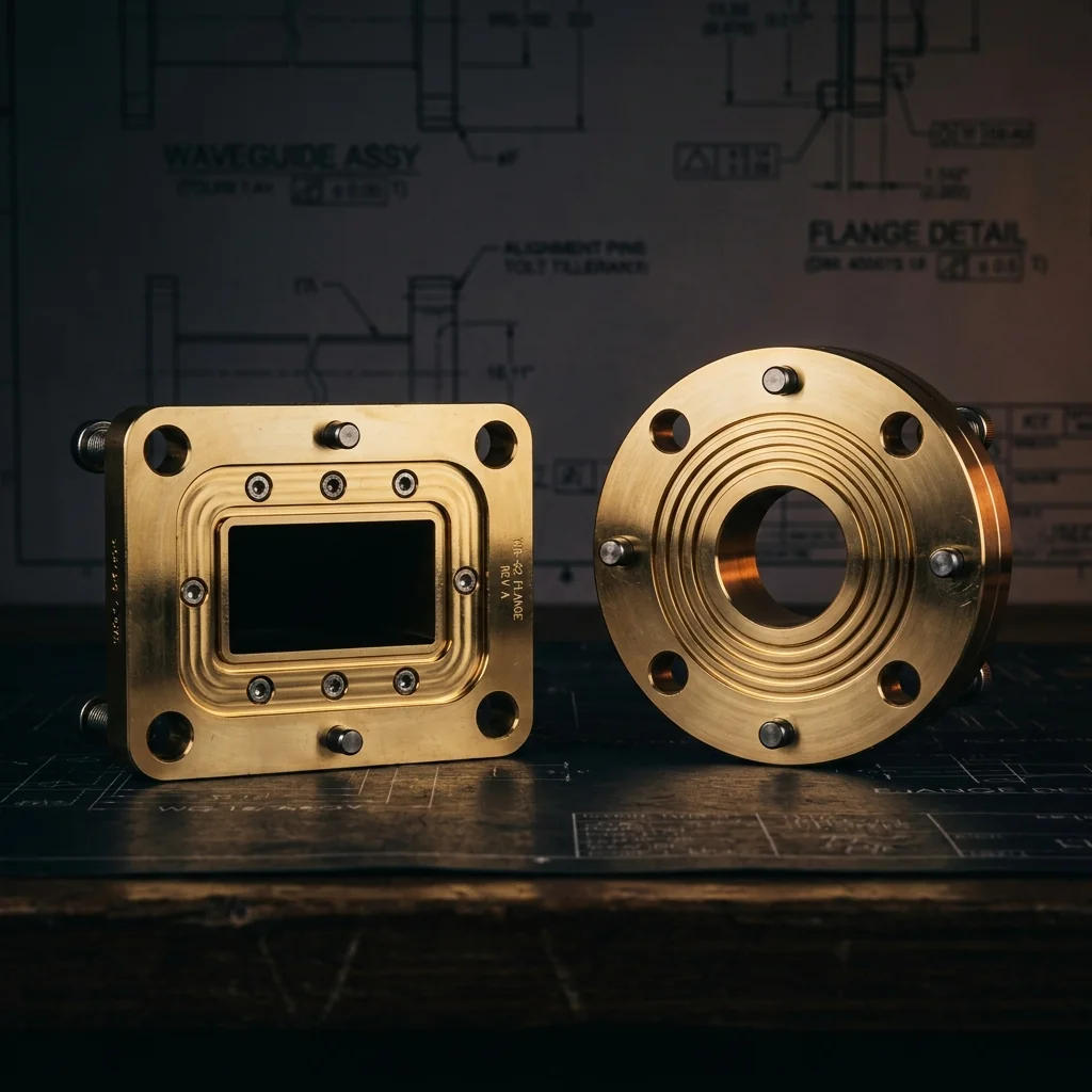
Complete dimensional reference for rectangular waveguide flange types. Technical drawings, MIL-DTL-3922 specifications, bolt patterns, alignment pin details, and compatibility guidelines for microwave and millimeter-wave systems.
Covers all standard flange configurations with engineering-grade dimensional tables you can reference during design, procurement, and integration.
Industry Insights
Technical articles, engineering deep-dives, and analysis from the RF Essentials team.