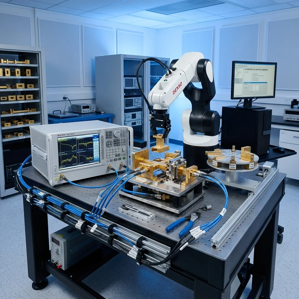
Waveguide component manufacturers face an escalating quality challenge: as operating frequencies push into W-band (75-110 GHz) and beyond, the acceptable tolerance window for insertion loss and return loss narrows while the measurement uncertainty of manual test procedures widens. At Ka-band, a skilled technician can achieve repeatable flange connections with ±0.02 dB insertion loss variation between connection cycles. At W-band, that same technician produces ±0.08 to ±0.15 dB variation because flange alignment becomes critical at the smaller waveguide apertures, and torque inconsistencies create measurable changes in the flange interface impedance.
Automated waveguide test systems address this problem by removing operator variability from the measurement process. A properly designed automated system controls the VNA calibration sequence, the device connection procedure, the torque applied to waveguide flanges, and the environmental conditions during measurement. The result is measurement uncertainty reduction of 40% to 60% compared to manual procedures, combined with throughput improvements that make 100% production testing economically viable.
1. Architecture of an Automated Test System
A production-grade automated waveguide test system consists of five subsystems working in coordination:
- Vector Network Analyzer: The core measurement instrument, typically a 4-port VNA covering the band of interest with frequency extension modules for waveguide bands above 67 GHz. The VNA provides S-parameter data that characterizes insertion loss, return loss, isolation, and phase response of the device under test (DUT).
- Calibration Automation: Motorized or pneumatic calibration standard changers that cycle through Short, Offset Short, Load, and Thru standards without operator intervention. This eliminates the connector handling variability that dominates calibration uncertainty in manual procedures.
- DUT Fixturing: Precision fixtures with controlled-torque flange connections that hold the waveguide DUT in a repeatable position and apply consistent flange bolt torque (typically 8 to 12 in-lb for standard UG-style flanges). Alignment pins ensure the waveguide apertures are centered within ±0.001 inches.
- Environmental Control: Temperature-stabilized test chambers or enclosures that maintain the VNA, cables, and DUT within ±1°C during the measurement sequence. Temperature drift is the dominant source of systematic error in long measurement sessions.
- Software Control: A measurement executive that sequences the calibration, connects the DUT, acquires data, applies limit testing, generates reports, and flags out-of-specification units. The software also manages calibration intervals and tracks measurement system health metrics.
2. Calibration Strategy for Automated Systems
The calibration approach directly determines the measurement uncertainty floor of the system. For waveguide test systems, TRL (Thru-Reflect-Line) calibration produces lower residual error than SOLT (Short-Open-Load-Thru) at frequencies above 40 GHz because TRL standards can be manufactured with tighter dimensional tolerances than broadband matched loads at millimeter wave frequencies.
| Calibration Method | Residual Directivity | Source Match | Best Frequency Range |
|---|---|---|---|
| SOLT (Manual) | 30-40 dB | 30-38 dB | DC to 40 GHz |
| SOLT (Automated) | 35-45 dB | 35-42 dB | DC to 40 GHz |
| TRL (Manual) | 38-48 dB | 38-45 dB | Narrowband, any frequency |
| TRL (Automated) | 42-52 dB | 42-50 dB | Narrowband, any frequency |
| Multi-Line TRL (Automated) | 45-55 dB | 45-52 dB | Broadband waveguide |
Calibration Interval Optimization: In a production environment, re-calibration is required whenever the measurement uncertainty budget indicates that drift has consumed the allocated margin. For manual systems, this typically means re-calibrating every 2 to 4 hours. Automated systems with temperature control maintain calibration validity for 8 to 12 hours, reducing non-productive calibration time by 60% and increasing the number of DUTs measured per shift.
3. Fixture Design Principles
The test fixture is the interface between the calibrated reference planes of the VNA and the flanges of the DUT. At millimeter wave frequencies, every aspect of this interface matters:
Flange alignment: Misalignment between the fixture and DUT waveguide apertures creates a discontinuity that appears as increased return loss and measurement uncertainty. Automated fixtures use precision alignment pins (dowel pin or anti-cocking designs per IEEE 1785) to center the apertures within ±0.0005 inches. The waveguide straight sections used in fixture construction must meet surface flatness requirements of 0.0002 inches at the flange face.
Torque control: Inconsistent bolt torque changes the contact pressure at the flange interface, affecting both the RF seal and the mechanical alignment. Automated fixtures use pneumatic or servo-driven torque drivers that apply the specified torque (±0.5 in-lb) to each bolt in a defined sequence. This eliminates the 0.03 to 0.10 dB insertion loss variation that manual torquing introduces at W-band and above.
Repeatability verification: A well-designed fixture produces a connection repeatability of ±0.005 dB insertion loss and ±0.3 dB return loss across 100 connection cycles at Ka-band. At W-band, achievable repeatability is ±0.01 dB insertion loss and ±0.5 dB return loss. These numbers should be verified during fixture qualification using a golden DUT measured 50 or more times.
4. Measurement Uncertainty Analysis
Every production measurement must be accompanied by an uncertainty statement to determine whether the measured result proves compliance with the specification. The total measurement uncertainty combines contributions from the VNA itself (noise floor, linearity, drift), the calibration residual errors (directivity, source match, load match), the fixture repeatability, and the environmental stability.
For a typical automated system measuring waveguide termination loads at Ka-band, the expanded uncertainty (95% confidence) for return loss measurement is ±0.8 dB for a DUT with 25 dB return loss. This means a measured value of 25.0 dB guarantees that the true return loss lies between 24.2 and 25.8 dB. If the specification requires 23 dB minimum return loss, the 25.0 dB measurement provides adequate margin. But a measurement of 23.5 dB would overlap with the specification limit and require a guard-band decision.
5. Throughput Considerations
The economic justification for automated test systems depends on achieving sufficient throughput to amortize the capital investment. A typical automated waveguide test cycle includes:
- DUT loading and fixture connection: 15-30 seconds
- S-parameter sweep (201 points, 10 Hz IF bandwidth): 5-15 seconds
- Data processing and limit testing: 1-2 seconds
- Report generation and DUT unloading: 10-15 seconds
Total cycle time of 30 to 60 seconds per DUT enables 60 to 120 units per hour, compared to 8 to 15 units per hour for a skilled operator performing manual measurements with the same VNA. At production volumes above 200 units per month, the automated system typically pays back its capital cost within 12 to 18 months through labor savings and reduced scrap from measurement errors.
6. RF Essentials Test Infrastructure
RF Essentials uses automated VNA-based test systems for 100% production testing of our waveguide components from WR-28 (Ka-band) through WR-03 (sub-THz). Every termination load, straight section, and bend ships with measured S-parameter data traceable to our calibrated reference standards. Our test infrastructure ensures that the specifications printed on our datasheets represent verified, measured performance rather than typical or simulated values.
Every RF Essentials waveguide component ships with measured S-parameter data from our automated test systems. Traceable calibration, controlled torque, and temperature-stabilized measurement environments ensure the numbers on your datasheet reflect real performance.