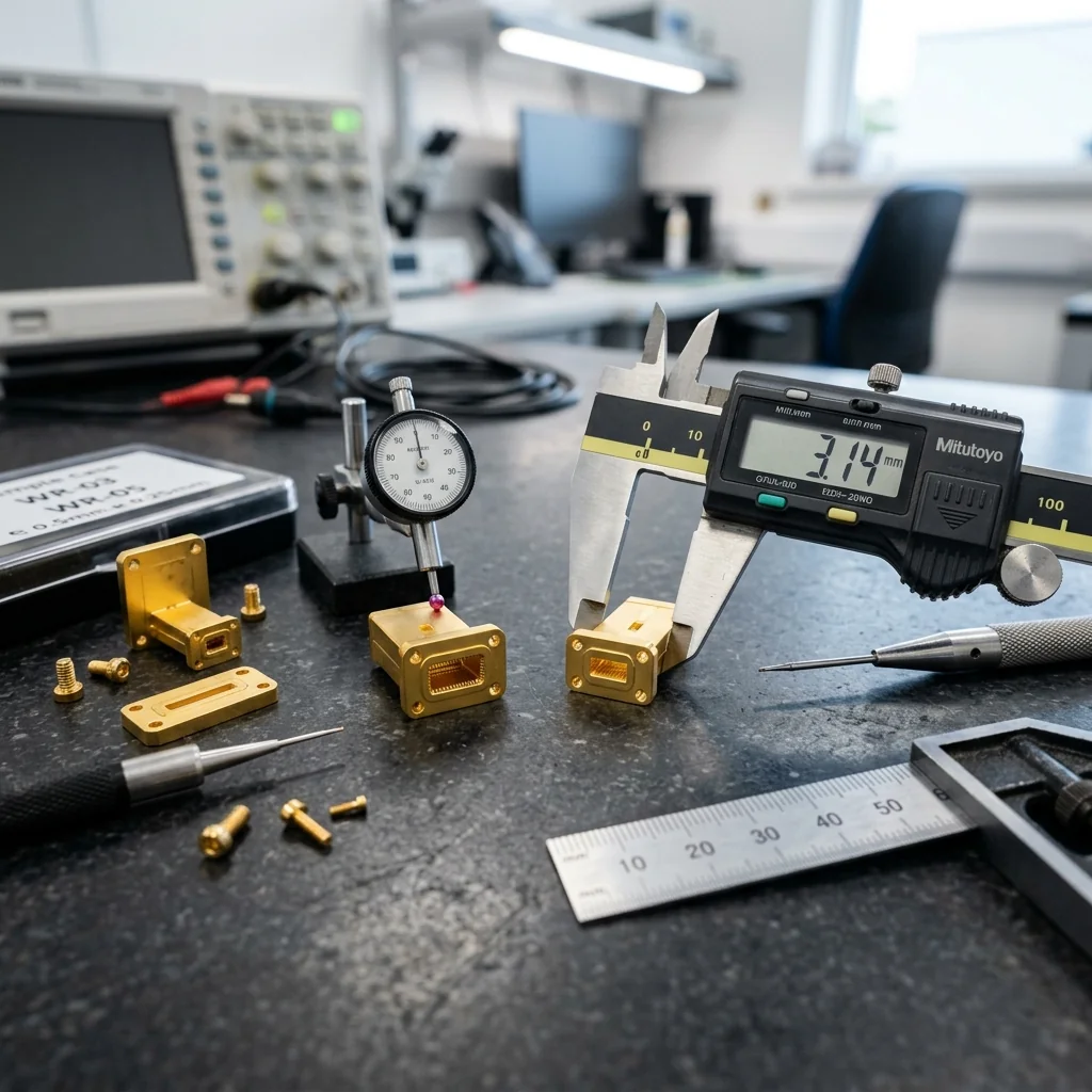
RF Essentials is pleased to announce a significant expansion of our sub-millimeter waveguide product portfolio. Effective immediately, we are offering full production runs of WR-03 (220 to 330 GHz) and WR-05 (140 to 220 GHz) waveguide components including straight sections, E-plane and H-plane bends, precision termination loads, transitions, and custom assemblies. This expansion responds to accelerating demand from the 6G research community, terahertz imaging laboratories, and radio astronomy programs that require high-precision passive waveguide at frequencies above 140 GHz.
Our St. Petersburg, Florida manufacturing facility has invested in new micro-machining tooling and inspection capabilities specifically for sub-millimeter waveguide production. The internal channel dimensions at WR-03 (0.034" x 0.017") and WR-05 (0.051" x 0.0255") demand tolerances tighter than ±0.0002 inches to maintain acceptable VSWR and insertion loss performance across the operating band.
Why Sub-Millimeter Waveguide Matters Now
Research programs worldwide are pushing into the 100 to 400 GHz frequency range, driven by several converging trends. The 6G wireless communications roadmap targets the 140 GHz and 220 GHz atmospheric windows for ultra-high-capacity backhaul and access links. Terahertz imaging systems for security screening, medical diagnostics, and non-destructive testing operate primarily in the WR-05 and WR-03 bands. Radio astronomy receivers for submillimeter spectroscopy require precision waveguide feed networks at these frequencies.
Until recently, sub-millimeter waveguide was available only through specialty European manufacturers with lead times of 16 to 24 weeks and minimum order quantities that excluded small research programs. RF Essentials aims to change that equation by offering standard catalog components with 4 to 6 week lead times and no minimum order requirement.
Product Specifications
| Parameter | WR-05 (140-220 GHz) | WR-03 (220-330 GHz) |
|---|---|---|
| Internal Dimensions | 0.051" x 0.0255" | 0.034" x 0.017" |
| Flange Type | UG-387/U-M (IEEE 1785) | UG-387/U-M (IEEE 1785) |
| Insertion Loss (Straight, per inch) | 0.15-0.25 dB | 0.25-0.40 dB |
| VSWR (Straight Section) | 1.05:1 typical | 1.08:1 typical |
| Surface Finish | 8 µin Ra (gold plated) | 4 µin Ra (gold plated) |
| Material | OFHC Copper, gold plated | OFHC Copper, gold plated |
| Dimensional Tolerance | ±0.0003" | ±0.0002" |
| Available Components | Straights, bends, twists, terminations, transitions | Straights, bends, terminations, transitions |
Manufacturing Challenges at Sub-Millimeter Frequencies
Machining waveguide channels with cross-sections smaller than a millimeter requires fundamentally different approaches than standard microwave waveguide production. At WR-03, the broad wall dimension of 0.034 inches (0.864 mm) approaches the practical limit of conventional end-mill machining. Our approach uses a combination of micro-end-mill CNC machining and wire EDM to achieve the required dimensional accuracy and surface finish.
Precision at Scale: At 300 GHz, a 0.001" dimensional error in the WR-03 channel width shifts the cutoff frequency by approximately 8 GHz. This means the difference between a waveguide that works and one that does not can be smaller than the thickness of a human hair. Our quality process includes 100% dimensional inspection using optical coordinate measurement with ±0.0001" resolution.
Surface finish is equally critical. Conductor loss in waveguide scales with surface roughness relative to skin depth. At 300 GHz, the skin depth in copper is approximately 0.12 micrometers. Surface roughness values that are acceptable at Ka-band become significant loss contributors at sub-THz frequencies. Our gold plating process achieves Ra values below 4 µin (0.1 µm) on the internal waveguide surfaces, minimizing excess conductor loss from surface scattering.
Applications Driving Demand
The expansion of our WR-03 and WR-05 product lines supports three primary application areas:
- 6G Research and Development: University and corporate research labs building prototype transceivers at 140 GHz and above for next-generation wireless communications. These programs need standard waveguide sections, bends, and transitions to construct test benches and prototype RF front ends.
- Terahertz Imaging and Spectroscopy: Security imaging systems, pharmaceutical quality inspection, and materials characterization using continuous-wave and pulsed THz sources coupled through waveguide feed networks.
- Radio Astronomy Receivers: Millimeter and submillimeter wave heterodyne receivers for spectral line observation. These instruments require ultra-low-loss waveguide feeds with precisely controlled VSWR to preserve the noise temperature of cryogenic mixers.
Ordering and Custom Capabilities
Standard WR-03 straight waveguide and WR-05 straight waveguide sections are available in lengths from 0.5 inches to 6 inches. E-plane and H-plane bends are available in 90-degree configurations with swept radius designs optimized for minimum insertion loss.
For custom assemblies, our engineering team works directly with researchers and system integrators to design multi-component waveguide assemblies with specified overall length, bend configurations, and interface transitions. We provide full S-parameter test data measured on our sub-THz VNA test bench for every production unit.
For pricing and availability, contact our applications engineering team through our online quote request form or call our St. Petersburg facility directly.
Browse our expanded WR-03 and WR-05 product lines. Standard and custom components available with 4-6 week lead times. Full VNA test data included with every order.