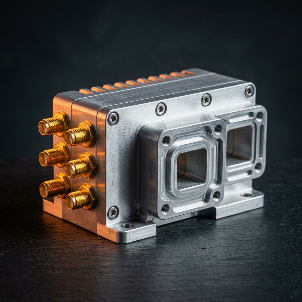
RF
Upconverters
IF-to-RF frequency conversion modules from 2 GHz to 52.5 GHz. Synthesized local oscillators, digital gain control, and high output power for satellite uplinks, radar transmitters, telemetry, and test systems.
Precision IF-to-RF Frequency Translation
RF Essentials upconverters translate lower-frequency IF or L-band signals to higher RF and millimeter-wave frequencies for transmission. Each unit features synthesized or externally referenced local oscillators, digitally controlled attenuation, and high conversion gain with low variation across the operating band.
Available in broadband microwave (2-18 GHz), Ka-band (33-36 GHz), Q-band (43.0-43.5 GHz), and U-band (47.5-52.5 GHz) configurations. All models support digital gain control, remote configuration, and integration into rack-mount, laboratory, or ruggedized deployment platforms.
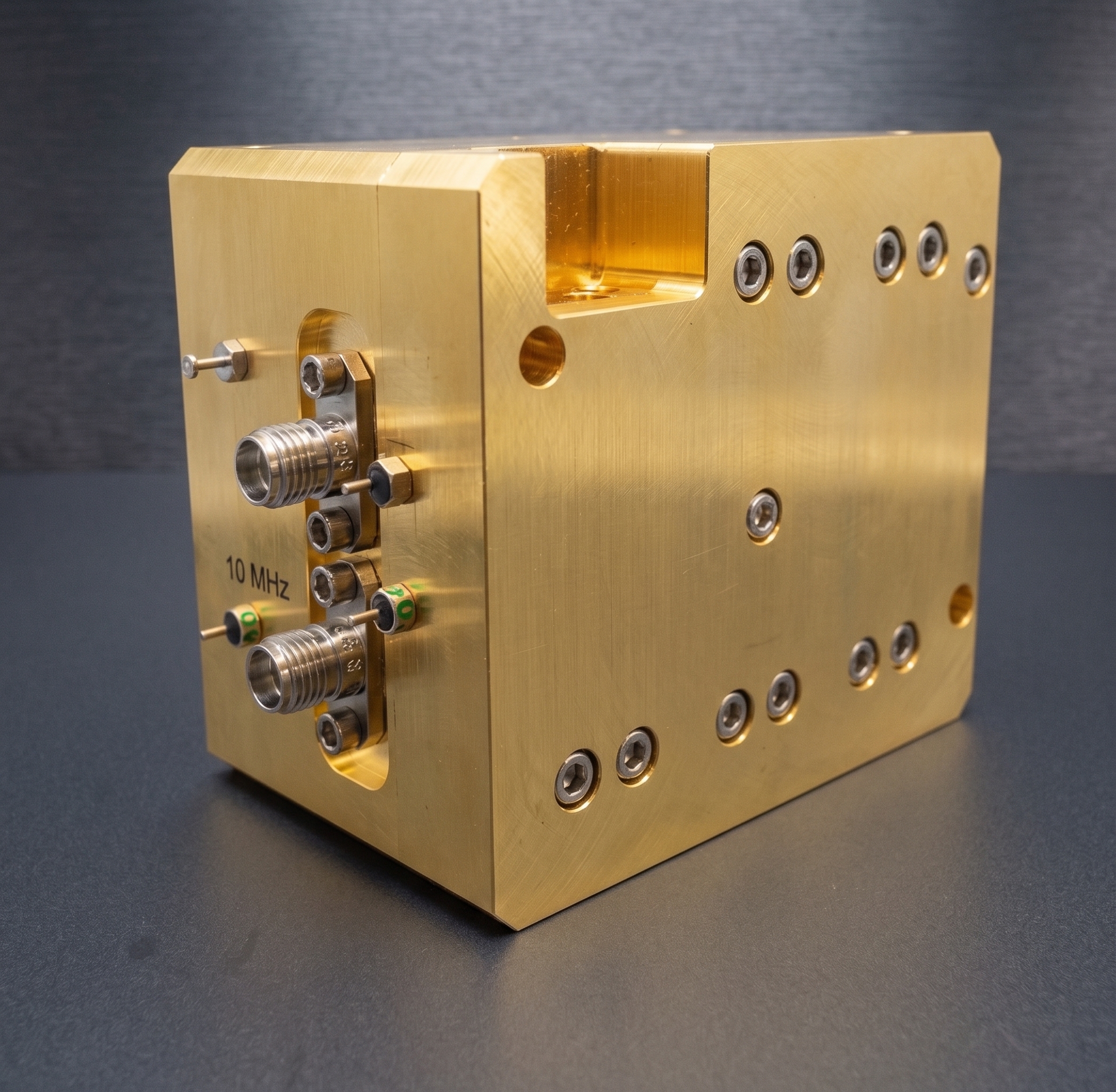
Upconverter Models by Frequency Band
Each row represents a specific upconverter model optimized for its target frequency band. Key specifications include RF output range, IF input range, conversion gain, output power, and control interface. Custom frequency plans and packaging available on request.
4 Upconverter Models| Band | RF Output | IF Input | Conv. Gain | Output Power | Attenuation | LO Type | RF Interface | Control |
|---|---|---|---|---|---|---|---|---|
| Broadband | 2 – 18 GHz | 500 MHz – 4 GHz | > 28 dB | 27 dBm | Digital | Synthesized | SMA (F) | RJ45 / GUI |
| Ka-Band | 33 – 36 GHz | 8.5 – 11.5 GHz | 33 dB (HiP) | 30 dBm P1dB | 0-24 dB / 1 dB | External | WR-28 | D-Sub |
| Q-Band | 43.0 – 43.5 GHz | 950 – 1450 MHz | 30 dB | 5 dBm P1dB | 0-30 dB / 0.5 dB | Internal | WR-22 | Digital |
| U-Band | 47.5 – 52.5 GHz | DC – 10 GHz | 40 dB | +40 dBm | 22 dB digital | Synthesized | Waveguide | GUI / API |
All specifications are typical at +25 °C. Actual performance may vary. Contact engineering for detailed datasheets, custom frequency plans, and environmental packaging options.
Up-Downconverter Models
Combined up-downconverter modules provide both transmit (IF-to-RF) and receive (RF-to-IF) frequency conversion in a single integrated package. These bidirectional units simplify transceiver architectures for SatCom terminals, radar systems, and full-duplex test benches.
3 Up-Downconverter Models| Band | Uplink RF | Downlink RF / IF | Tx Output | Rx Gain / Output | LO Type | RF Port | Ref / IF Port |
|---|---|---|---|---|---|---|---|
| Ka-Band | 35.61 GHz | 4 – 5.5 GHz | 0 to +6 dBm | -10 to +10 dBm | Internal VCO | K-Type | N-Type |
| U / Q-Band | 47.2 – 51.4 GHz | 37.5 – 42.5 GHz | 26 dBm (Sat) | −86 dBm (Repeater In) | Internal PLO | WR-19 | 10 MHz SMA (Ref) |
| W-Band | 95 – 100 GHz | 2.1 GHz (Fixed) | ~20 dBm (30 dB gain) | 35 dB gain / 5 dB NF | Internal VCO | WR-10 | — |
Up-downconverter specifications are typical at +25 °C. Bidirectional modules include both upconversion and downconversion signal paths in a single chassis. Contact engineering for full transceiver datasheets and custom configurations.
Need a specific frequency plan or custom configuration?
Our engineering team can provide pricing, datasheets, and custom configurations for any upconverter in the catalog. Multichannel architectures and ruggedized packaging available.
Design & Performance
28 to 40 dB of conversion gain across the product line reduces external amplification requirements and simplifies transmit chain architecture.
Digitally controlled synthesized local oscillators with fine frequency resolution, supporting CW, sweep, and hop modes for agile signal generation.
Precision digital step attenuators with 0.5 to 1.0 dB resolution for repeatable output level management without external pads or gain stages.
High image rejection (up to 60 dB), strong harmonic suppression, and embedded RF cavity filtering deliver clean output spectra across the tuning range.
Ka-band model supports phase-matched dual-channel outputs for orthomode transducer interfaces, enabling horizontal and vertical polarization paths.
Commercial rack-mount, laboratory, airborne, and ruggedized enclosure options. Designed for deployment in controlled environments and harsh field conditions.
Where Our Upconverters Perform
RF Essentials upconverters support a wide range of transmit architectures across commercial, defense, and research environments. From satellite ground terminals to millimeter-wave test benches, these modules provide the frequency translation performance your system requires.
- Satellite Uplink Systems
- Radar Transmit Chains
- Electronic Warfare
- Telemetry & Aerospace
- Point-to-Point Microwave
- Test & Measurement
- 5G / 6G Research
- Wideband Signal Generation
Frequently Asked Questions
An RF upconverter translates a lower-frequency signal, such as an intermediate frequency (IF) or L-band input, to a higher RF or millimeter-wave output frequency using a mixer and local oscillator. This frequency translation is essential in transmit chains for satellite communications, radar, telemetry, and wireless systems where the signal must be moved to the operating band before amplification and transmission.
RF Essentials upconverters cover four frequency ranges: 2 to 18 GHz (broadband microwave), 33 to 36 GHz (Ka-band), 43.0 to 43.5 GHz (Q-band), and 47.5 to 52.5 GHz (U-band). Each model is optimized for its target band with appropriate waveguide or coaxial RF output interfaces.
Conversion gain is the net signal gain provided by the upconverter during frequency translation from IF to RF. Values range from 28 dB to 40 dB depending on the model. Higher conversion gain reduces the need for external amplification stages in the transmit chain, simplifying system architecture and improving signal-to-noise performance.
Yes. All four upconverter models are designed for satellite uplink applications. The Ka-band model supports dual-channel phase-matched outputs for orthomode transducer (OMT) interfaces, while the U-band model provides high output power up to +40 dBm for demanding link budgets. Each unit features digitally controlled attenuation and synthesized or external LO options for system-level integration.